Chilled Cast Iron
24 August 1998


Page 1 | Page 2 | Page 3 | Page 4 | Page 5 | Page 6 | Page 7 | Page 8
Material Science II, Assignment NO.1
|
Aim: |
To observe the microstructure of the Chilled Cast Iron under microscope, and to familiarise the operation involved. |
|
Apparatus: |
Cutter or Hammer, Grinding Machine, Hot Mounting Machine, Fine Polishing machine, Etching liquid, and Metallurgical Microscope. |
|
Description of Material: |
|
|
Chilled Cast Iron is made by casting the molten metal against a metal chillier, resulting in a surface of white cast iron. A softer grey iron core backs up this hard, abrasion-resistant white iron surface. This case-core structure is obtained by careful control of the overall alloy composition and adjustment of the cooling rate. A chilled cast iron casting can be produced by adjusting the composition of the iron so that the normal cooling rate at the surface is just fast enough to produce white cast iron while the slower cooling rate below the surface will produce grey iron. The depth of chill decreases and the hardness of the chilled zone increases with increasing carbon content. Chromium is used in small amounts to control chill depth, 0.01 percent chromium will neutralise about 0.015 percent silicon. Because of the formation of chromium carbides, chromium is used in amount of 1 to 4 percent in chilled iron to increase hardness and improve abrasion resistance. It also stabilises carbide and suppresses the formation of graphite in heavy sections. When added in amounts of 12 to 35 percent, chromium will impart resistance to corrosion and oxidation at elevated temperatures. A constant chill depth may be obtained by using a combination of alloying elements that have opposite effects. Since nickel reduces chill depth, it is common practice to add chromium, which increases chill depth, to neutralise the nickel and result in a constant chill depth. Uses of Chilled Cast Iron Chilled-iron casting is used for railway-car wheels, crushing roll, stamp shoes and dies, and many heavy-duty machinery parts. |
|
Page 1 | Page 2 | Page 3 | Page 4 | Page 5 | Page 6 | Page 7 | Page 8
|
The cutting operation is to cut a small sample of the Chilled Cast Iron so that the structure of the specimen could be examined under a Metallurgical Microscope. The operating Machine has a thin circular disk that is suitable of cutting abrasive materials, and rotating at high revolutions at speeds of 3500 rpm, the rotating speed depend on which metal or alloy is been cut.. As the sample is been cut it is been cooled down by a lubricant (i.e. water), this is because the cutting produces enormous amount of heat and could change the structure of the specimen under investigation. In the case of our specimen, Chilled cast Iron we know that it is hard and abrasive, we could attain a sample of it by hammering it down using a hammer. A typical Cutting machine is shown below.
Page 1 | Page 2 | Page 3 | Page 4 | Page 5 | Page 6 | Page 7 | Page 8 |
|
The specimen is then hot mounted or cold mounted Hot Mounting operation is done with a mounting press similar to one shown in the picture to the right. The procedure to follow are as follows: - First we close the valve and then pump up the handle to raise the stage, now we place the specimen facing down on the stage, over which the phenolia pre mould is placed, the diameter of the pre mould is around 32mm. Next step is to open the valve tighten the top and close the valve and pump up to pre-load pressure, the system is left like this for some time till the pressure drops slightly. We now raise the pressure to 29Mpa, put on the heater and leave it on until the pressure drops to zero. After the pressure dropping to zero remove the heater and replace it with a heat sink and release the pressure and open up the valve and remove the top, close the valve and pump up the stage and take off the specimen. Cold Mounting: Another method of mounting is cold mounting that is much simpler and uses chemicals to mould it. This method requires Acrylic Powder, cold mounting liquid, and a flexible rubber type container. Procedure to be followed are as follows:- First mix the Acrylic powder with the cold mounting liquid in a ratio of 2:1, mix well until it flows nicely, place the specimen's polished face down in the rubber container and pour the mixture into the rubber container. Leave it to hardened at room temperature. Once hardened remove the mould from the rubber container. The mould should look like the figure to the right.
|
Simplimet 2 Mounting Press
|
Page 1 | Page 2 | Page 3 | Page 4 | Page 5 | Page 6 | Page 7 | Page 8
|
The Specimen is then grind on the Machines shown below, the purpose of doing so is to obtain a smooth surface, by rubbing the flat surface of the specimen on increasingly fine grinding papers. The paper sizes used on the grinding wheels are normally from 180 grit (coarse), 220, 320, 400 up to 600 or 1000 grit (fine). In our case we used the following grit sizes, 220, 320, 400 and 600. The operation is carried out on rotating grinding wheels with water used as lubricant, which is supplied throughout the grinding operation. Lubricant prevents overheating the sample, minimises smearing of soft metals, and also provides a rinsing action to flush away surface removal products so the paper will not become clogged. During the grinding operations the specimen is moved perpendicular to the existing scratches, when it is been moved from one grinding wheel to another. This is to make sure that the scratches in one direction are totally eliminated by the operation on the next paper. An even pressure is applied to the specimen i.e. to prevent wrapping. The grinding is followed till the last grinding wheel paper has reached, and the surface is flat and all the scratches are no longer visible. |
|
Wheel No.1 and No.2
|
Wheel No.3 and No.4
|
|
Page 1 | Page 2 | Page 3 | Page 4 | Page 5 | Page 6 | Page 7 | Page 8 |
|
|
Before proceeding to fine polishing the specimen is washed with soap and dried. Then the specimen is fine polished on rotating wheel covered with a special cloth usually selvyt, and a diamond paste polishing agent with a grade of 6mm and 1 mm on the two wheels. A lubricant is normally used with diamond paste known as a diamond extender fluid. The purpose of the lubricant is to keep the diamond particles free and helps with cleanliness; it's actually a dispersing agent. During the operation the specimen is held firmly without applying to much pressure because applying too much pressure will cause the specimen's microstructure to appear incorrectly. To ensure an evenly polished surface the specimen is rotated in the opposite direction of the wheel. The specimen is washed thoroughly with soap each time it changes the wheel and also after polishing. After polishing the specimen looks shinny and without any scratches on. Next is the Etching operation. |
|
|
Etching Operation The purpose of etching is to make visible the many structural characteristics of the metal or alloy by chemically attacking the part of the specimen with a suitable reagent. The process must be such that the various parts of the microstructure may be clearly differentiated. Etching is normally done by immersing the specimen with the polished side up with the etching solution in a small dish. As our specimen is chilled cast iron we use the Hydrochloric, Picric, Nitric acid and Methanol mixed as the reagent. The specimen is swirled when its in the dish, this is to make sure fresh solution is moving over the surface. The etching time varies depending on different materials. When the specimen is etched the specimen becomes blurred and dull and must be immediately removed and washed and dried, this is because reagent will continue to react even after its removal from the dish. The specimen is then viewed under a microscope and the grain structure looks like the picture shown on the right. |
Microstructure of Chilled Cast Iron |
Page 1 | Page 2 | Page 3 | Page 4 | Page 5 | Page 6 | Page 7 | Page 8
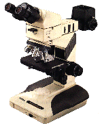
Metallurgical Microscope
Optical Microscopes are the most commonly used microscopes in any laboratories nowadays for examining the microstructure of metals, alloys etc. Some are used for photographing the structure of the specimen as I have done on the previous page. A typical microscope looks like shown in the picture below.
The microscope shown below has several objective lenses so that different magnifications can be used. The highest magnification is about 1000X, but as the magnification increases the clarity of the image decreases. Different sizes of objective lenses could be fitted depending on the required detail of the specimen.

Microscope of the type shown above could easily cost a couple of thousand Rands, so great care must be taken while in using it.
Page 1 | Page 2 | Page 3 | Page 4 | Page 5 | Page 6 | Page 7 | Page 8
Phase Diagram

Bibliography:
Introduction to Physical Metallurgy, 2nd Edition, Avner
And Internet:
Manchester Materials Science Centre, UMIST and University of Manchester. http://www.umist.ac.uk/MatSci/Page 1 | Page 2 | Page 3 | Page 4 | Page 5 | Page 6 | Page 7 | Page 8